Next
Move an arm
Viam’s motion planning tools allow you to automate the intelligent movement of your machines. You can:
For example, instead of sending individual commands to each motor of a robotic arm, you can use one motion planning command to move the arm smoothly to a specific position while avoiding obstacles and keeping a gripper upright.
You can move the following components with the motion service:
You can use the following components to augment motion planning and navigation:
Viam’s frame system allows you to describe the spatial relationship between the components in your robot. You configure your machine’s frames once, and Viam keeps track of the frames as they move. This means you can send motion service commands using a consistent coordinate system, regardless of where the components are at a given time.
You must configure frames before you can use the motion service.
For example, if you want to command an arm to move to coordinates of (300, 0, 0) millimeters, you first need to decide on the origin (0, 0, 0) and the directions of the x, y, and z axes of the world coordinate system to give your coordinates meaning.
You then define the arm’s frame to describe its position and orientation relative to the world frame.
If you also have a gripper component, you define the gripper’s frame to describe its position and orientation relative to the arm, so that when the arm moves, the motion service knows where the gripper is as well.
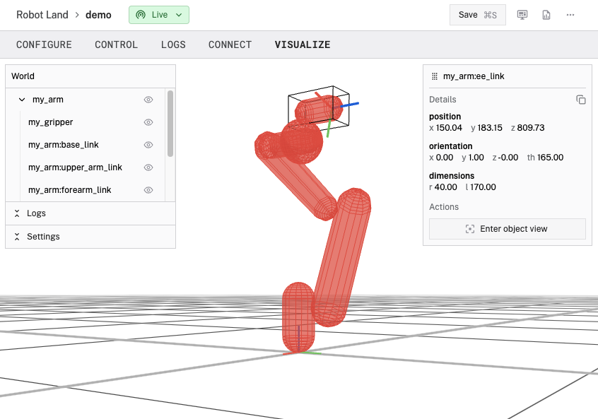
You can visualize your machine’s geometries and frames in the Viam app:
To visualize a component without moving any real-world hardware, configure a fake model to represent your component (for example, a fake arm), then follow the steps below using the fake component.
In Viam, navigate to your machine’s page.
Make sure your machine is live and connected to Viam. If your machine is not live, the visualization will not display.
Select the VISUALIZE tab.

Scroll to zoom, click and drag to tilt, and right-click and drag to pan.
Use the tree menu or click on the visualization to select a component, link, or other object to display its position, orientation, and dimensions.
You can go to the CONTROL tab, move your components, and then return to the VISUALIZE tab to see the updated visualization.
Was this page helpful?
Glad to hear it! If you have any other feedback please let us know:
We're sorry about that. To help us improve, please tell us what we can do better:
Thank you!